SRv6 ultra-scale - Imposition of 26 SRv6 uSIDs at Linerate
SRv6 ultra-scale - Imposition 26 SRv6 uSIDs at Linerate
Rakuten, Bell Canada and Cisco Systems are happy to report the successful validation of line rate insertion of 26 SRv6 uSIDs on the NCS 5700 Series platforms running Cisco IOS XR.
The NCS5700 Series line cards and routers are powered by Broadcom Jericho2 family NPUs, providing 400GigE interfaces to offer 4.8Tbps of interface bandwidth and 5.6Tbps to the fabric.
This report demonstrates the ultra-scale capability of the SRv6 solution. 26 is indeed 2 to 3 times better than the current MPLS deployed use-cases.
While reducing the number of layers (MPLS, VxLAN, and NSH are no longer needed), the SRv6 solution provides more power of service expression (Network Programming, Proposed Standard RFC 8986) and ultra-scale (as demonstrated in this report).
Demo Video
Demo Setup
The demo setup as illustrated in Figure 1 contains the ingress PE1 that will do the uSID imposition, connected to Ixia traffic generator ports via 400GbE interfaces.
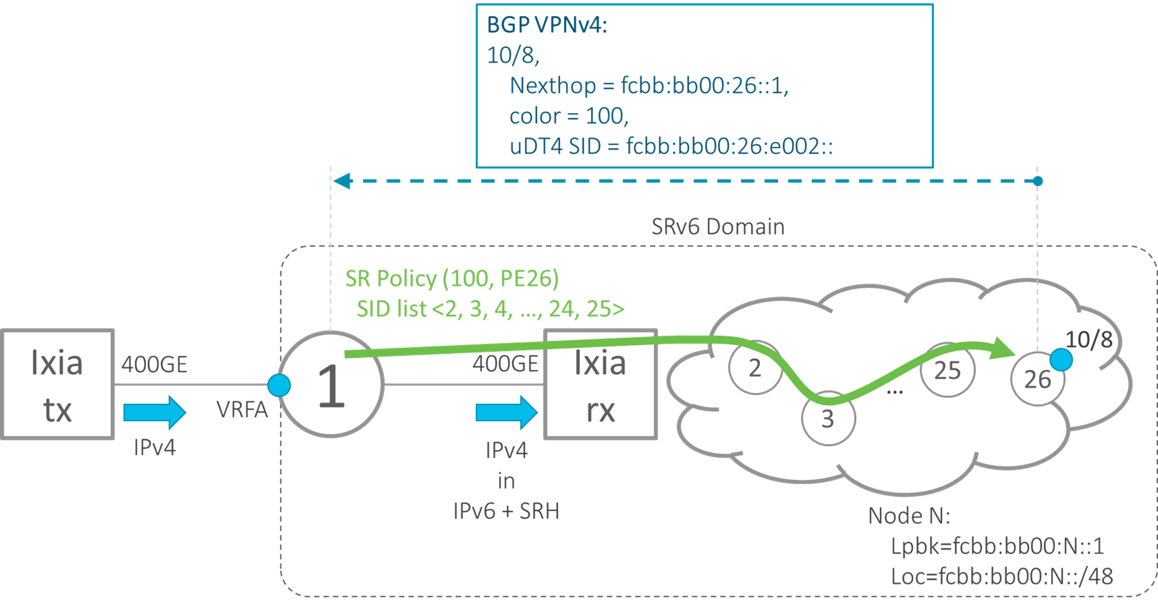 Figure 1: Demo setup
PE1 in this demo is a Cisco NCS-5508 chassis with NC57-18DD-SE linecard.
The simulated topology behind the Ixia receive port contains the egress PE26 and 24 nodes (numbered 2 to 25) that will be used as waypoints for the path from PE1 to egress PE26.
PE1 and PE26 are part of a VPN providing IPv4 connectivity.
PE26 advertises VPN route 10/8 towards PE1. The BGP nexthop is the loopback address of PE26, fcbb:bb00:26::1. With the service route, PE26 advertises the service SID fcbb:bb00:26:e002:: which is a combination of its uN SID and the uDT4 SID of this VRF.
PE26 also advertises a BGP color extended community 100 with the route, which identifies the SLA requested for this route. PE1 will use this color for its color-based Automated Steering into an SR Policy.
SR Policy on PE1
The SR Policy on PE1 uses and explicit segment-list with 24 uN SIDs (Prefix-SIDs), specifying the path to traverse 24 SIDs before ending on the egress PE26. The configuration on PE1 of the SR Policy with the explicit segment-list is shown in Example 1. The SR Policy’s color 100 and endpoint fcbb:bb00:26::1 match the color and nexthop of the VPNv4 service route advertised by PE26. Note: the configuration commands are subject to change.
Example 1: Configuration of SR Policy POL1 with explicit segment-list SL1
segment-routing
 traffic-eng
  segment-list SL1
   index 10 srv6 sid fcbb:bb00:2::
   index 20 srv6 sid fcbb:bb00:3::
   index 30 srv6 sid fcbb:bb00:4::
   index 40 srv6 sid fcbb:bb00:5::
   index 50 srv6 sid fcbb:bb00:6::
   index 60 srv6 sid fcbb:bb00:7::
   index 70 srv6 sid fcbb:bb00:8::
   index 80 srv6 sid fcbb:bb00:9::
   index 90 srv6 sid fcbb:bb00:10::
   index 100 srv6 sid fcbb:bb00:11::
   index 110 srv6 sid fcbb:bb00:12::
   index 120 srv6 sid fcbb:bb00:13::
   index 130 srv6 sid fcbb:bb00:14::
   index 140 srv6 sid fcbb:bb00:15::
   index 150 srv6 sid fcbb:bb00:16::
   index 160 srv6 sid fcbb:bb00:17::
   index 170 srv6 sid fcbb:bb00:18::
   index 180 srv6 sid fcbb:bb00:19::
   index 190 srv6 sid fcbb:bb00:20::
   index 200 srv6 sid fcbb:bb00:21::
   index 210 srv6 sid fcbb:bb00:22::
   index 220 srv6 sid fcbb:bb00:23::
   index 230 srv6 sid fcbb:bb00:24::
   index 240 srv6 sid fcbb:bb00:25::
  !
  policy POL1
   srv6
   !
   color 100 end-point ipv6 fcbb:bb00:26::1
   candidate-paths
    preference 100
     explicit segment-list SL1
The forwarding entry for SR Policy POL1 on PE1 is shown in Example 2. The Binding SID fcbb:bb00:1:e013:: and the SID stack with 24 SIDs are highlighted in the output.
The Binding SID is the key into the SR Policy. Any packet sent via this Binding SID, will be transmitted via the SR Policy.
Example 2: Forwarding entry of SR Policy POL1
RP/0/RP0/CPU0:J2-PE1# show segment-routing traffic-eng forwarding policy color 100

SR-TE Policy Forwarding database
--------------------------------

Color: 100, End-point: fcbb:bb00:26::1
  Name: srte_c_100_ep_fcbb:bb00:26::1
  Binding SID: fcbb:bb00:1:e013::
  Active LSP:
    Candidate path:
      Preference: 100 (configuration)
      Name: POL1
    Segment lists:
      SL[0]:
        Name: SL1
        Paths:
          Path[0]:
            Outgoing Interfaces: FourHundredGigE0/4/0/16
            Next Hop: 2001::1:2:2
            FRR Pure Backup: No
            ECMP/LFA Backup: No
            SID stack (Top -> Bottom): {fcbb:bb00:2::, fcbb:bb00:3::, fcbb:bb00:4::, fcbb:bb00:5::, fcbb:bb00:6::, fcbb:bb00:7::, fcbb:bb00:8::, fcbb:bb00:9::, fcbb:bb00:10::, fcbb:bb00:11::, fcbb:bb00:12::, fcbb:bb00:13::, fcbb:bb00:14::, fcbb:bb00:15::, fcbb:bb00:16::, fcbb:bb00:17::, fcbb:bb00:18::, fcbb:bb00:19::, fcbb:bb00:20::, fcbb:bb00:21::, fcbb:bb00:22::, fcbb:bb00:23::, fcbb:bb00:24::, fcbb:bb00:25::}
Looking on PE1 at the CEF entry of the SR Policy’s Binding SID fcbb:bb00:1:e013::, as illustrated in Example 3, shows that the segment-list with 24 segments is compressed into four uSID containers with six uSID in each container.
Example 3: CEF entry of SR Policy POL1 Binding SID fcbb:bb00:1:e013::
RP/0/RP0/CPU0:J2-PE1# show cef ipv6 fcbb:bb00:1:e013:: detail
fcbb:bb00:1:e013::/64, version 2649, SRv6 Endpoint uB6 (Insert.Red), internal 0x1000001 0x0 (ptr 0x9563c8e8) [5], 0x400 (0x94657670), 0x0 (0xa8fed168)
Updated Mar  7 22:34:32.190
 local adjacency to FourHundredGigE0/4/0/16

Prefix Len 64, traffic index 0, precedence n/a, priority 0
  gateway array (0x957c5320) reference count 1, flags 0x0, source rib (7), 0 backups
                [2 type 3 flags 0x8401 (0x94c4c0e8) ext 0x0 (0x0)]
  LW-LDI[type=3, refc=1, ptr=0x94657670, sh-ldi=0x94c4c0e8]
  gateway array update type-time 1 Mar  7 21:50:07.086
LDI Update time Mar  7 21:50:07.090
LW-LDI-TS Mar  7 22:34:32.190
   via 2001::1:2:2/128, FourHundredGigE0/4/0/16, 7 dependencies, weight 0, class 0 [flags 0x0]
    path-idx 0 NHID 0x0 [0x914e9310 0x0]
    next hop 2001::1:2:2/128
    local adjacency
    SRv6 H.Insert.Red SID-list {fcbb:bb00:2:3:4:5:6:7 fcbb:bb00:8:9:10:11:12:13 fcbb:bb00:14:15:16:17:18:19 fcbb:bb00:20:21:22:23:24:25}

    Load distribution: 0 (refcount 2)

    Hash  OK  Interface                 Address
    0     Y   FourHundredGigE0/4/0/16   2001::1:2:2
BGP VPNv4 service route
PE26 advertises the BGP VPNv4 route 10.0.0.0/8 to PE1. The route as received by PE1 is shown in Example 4.
The color 100 and nexthop fcbb:bb00:26::1 matches the color and nexthop of SR Policy POL1, therefore PE1 steers this route via this SR Policy’s Binding SID fcbb:bb00:1:e013::. This is shown in the output displayed in Example 4.
PE26 advertises the VPNv4 route with a uDT4 SID (behavior id=63) fcbb:bb00:26:e002::.
The output in Example 4 shows that a Prefix-SID Attribute is attached to the route with an SRv6 L3 Service TLV (PSID-Type:L3). This TLV carries an SRv6 SID Information sub-TLV that again carries an SRv6 SID Structure sub-sub-TLV (SSTLV in short).
To increase BGP Update packing efficiency, PE26 uses the “transposition” functionality in the SRv6 service SID advertisement (see draft-ietf-bess-srv6-services for details). Part of the service SID (fcbb:bb00:26::) is carried in the SRv6 L3 Service TLV, with the remaining part carried in the MPLS label field of the NLRI. The use if this transposition functionality is indicated in the SSTLV fields Tpose-len:16, Tpose-offset:48.
Example 4: BGP VPNv4 route 10.0.0.0/8 on PE1 as advertised by PE26
RP/0/RP0/CPU0:J2-PE1# show bgp vrf vrf-main 10.0.0.0/8 detail
BGP routing table entry for 10.0.0.0/8, Route Distinguisher: 100:1
Versions:
  Process           bRIB/RIB  SendTblVer
  Speaker              187327       187327
Last Modified: Mar  7 22:21:36.599 for 00:16:03
Paths: (1 available, best #1)
  Advertised to PE peers (in unique update groups):
    1.1.1.8
  Path #1: Received by speaker 0
  Advertised to PE peers (in unique update groups):
    1.1.1.8
  201
    fcbb:bb00:26::1 C:100 (bsid: fcbb:bb00:1:e013::) (metric 10) from fcbb:bb00:26::1 (100.1.1.2)
      Received Label 0xe0020
      Origin IGP, localpref 100, valid, internal, best, group-best, import-candidate, imported
      Received Path ID 0, Local Path ID 1, version 187327
      Extended community: Color:100 RT:100:1
      SR policy color 100, up, not-registered, bsid fcbb:bb00:1:e013::

      PSID-Type:L3, SubTLV Count:1
       SubTLV:
        T:1(Sid information), Sid:fcbb:bb00:26::, F:0x00, R2:0x00, Behavior:63, R3:0x00, SS-TLV Count:1
         SubSubTLV:
          T:1(Sid structure):
           Length [Loc-blk,Loc-node,Func,Arg]:[32,16,16,0], Tpose-len:16, Tpose-offset:48
      Source AFI: VPNv4 Unicast, Source VRF: vrf-main, Source Route Distinguisher: 100:1
The VRF CEF entry for 10.0.0.0/8 on PE1 is shown in Example 5.
This VRF route resolves on the Binding SID fcbb:bb00:1:e013:: of SR Policy POL1 and before steering into the SR Policy, it imposes the SID list fcbb:bb00:26:e002::, which is the compressed SID list of uN and uDT4 SIDs as advertised by PE26.
Example 5: VRF CEF entry of route 10.0.0.0/8 on PE1
RP/0/RP0/CPU0:J2-PE1# show cef vrf vrf-main 10.0.0.0/8
10.0.0.0/8, version 2014, SRv6 Headend, internal 0x5000001 0x30 (ptr 0xa7ad1868) [1], 0x0 (0x0), 0x0 (0x9c5d5d38)
 Updated Mar 23 14:01:09.907
 Prefix Len 30, traffic index 0, precedence n/a, priority 3
  gateway array (0xa7606448) reference count 2004, flags 0x2010, source rib (7), 0 backups
                [1 type 3 flags 0x48441 (0x8dbbe668) ext 0x0 (0x0)]
  LW-LDI[type=0, refc=0, ptr=0x0, sh-ldi=0x0]
  gateway array update type-time 1 Mar 23 10:57:11.679
 LDI Update time Mar 23 10:57:11.679

  Level 1 - Load distribution: 0
  [0] via fcbb:bb00:1:e013::/128, recursive

   via local-srv6-sid fcbb:bb00:1:e013::, 5 dependencies, recursive [flags 0x6000]
    path-idx 0 NHID 0x0 [0x91cfb520 0x0]
    recursion-via-/64
    next hop VRF - 'default', table - 0xe0800000
    next hop fcbb:bb00:1:e013:: via fcbb:bb00:1:e013::/64
    SRv6 H.Encaps.Red SID-list {fcbb:bb00:26:e002::}

    Load distribution: 0 (refcount 1)

    Hash  OK  Interface                 Address
    0     Y   FourHundredGigE0/4/0/16   2001::1:2:2
Traffic generator
We are now ready to start sending the IPv4 traffic into ingress PE1. PE1 will impose the SID list of 26 uSIDs on the packets using an outer IPv6 header with SRH and forward these encapsulated packets to the receive port of the Ixia traffic generator, as illustrated in Figure 2.
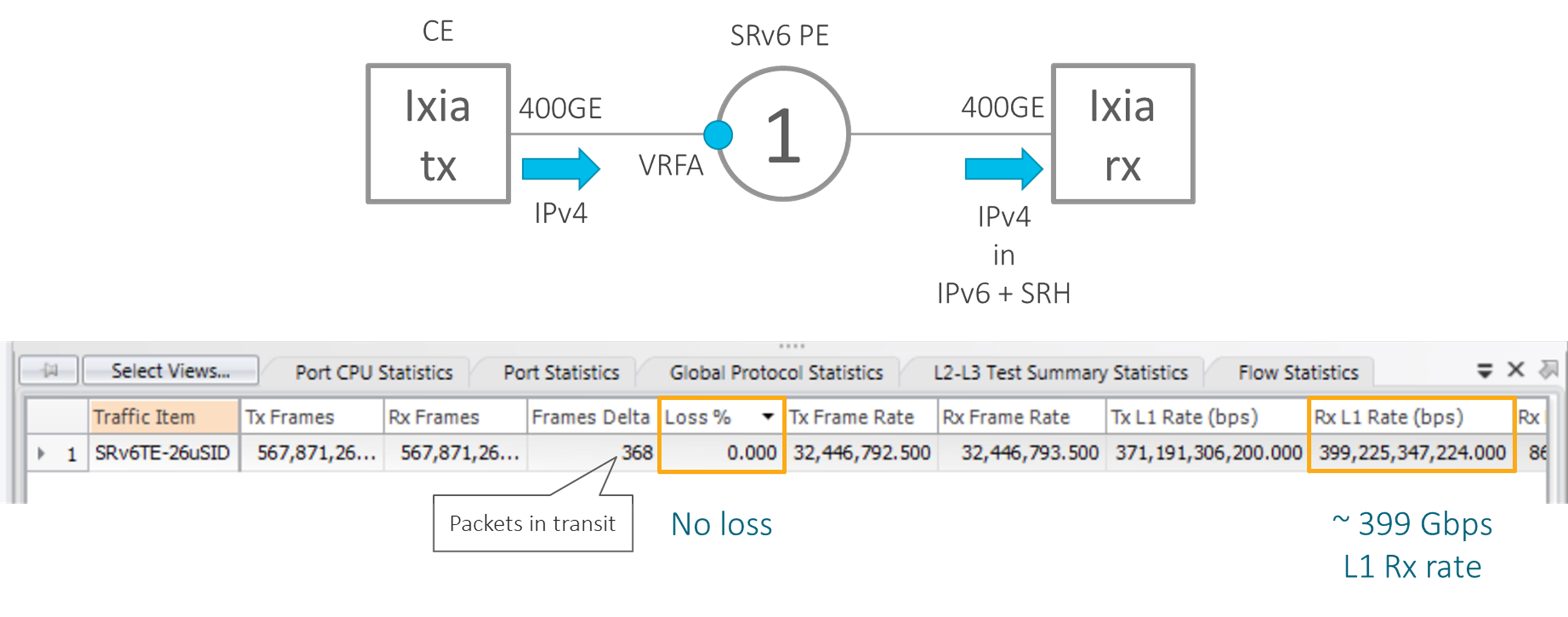 Figure 2: Screenshot of Ixia traffic statistics
At the bottom of Figure 2, a partial screenshot of the Ixia traffic generator is shown, showing the traffic statistics. Loss % is zero, no packets are lost. The “Frames Delta” field shows how many transmitted packets are still in transit.
The Layer 1 receive rate “Rx L1 Rate (bps)” is slightly above 399 Gbps, which is about the maximum rate that can be sent on a 400GbE interface.
Packet Capture
We capture some of the data packets as received by Ixia receive port and use Wireshark to display a packet. A wireshark screenshot is shown in Figure 3.
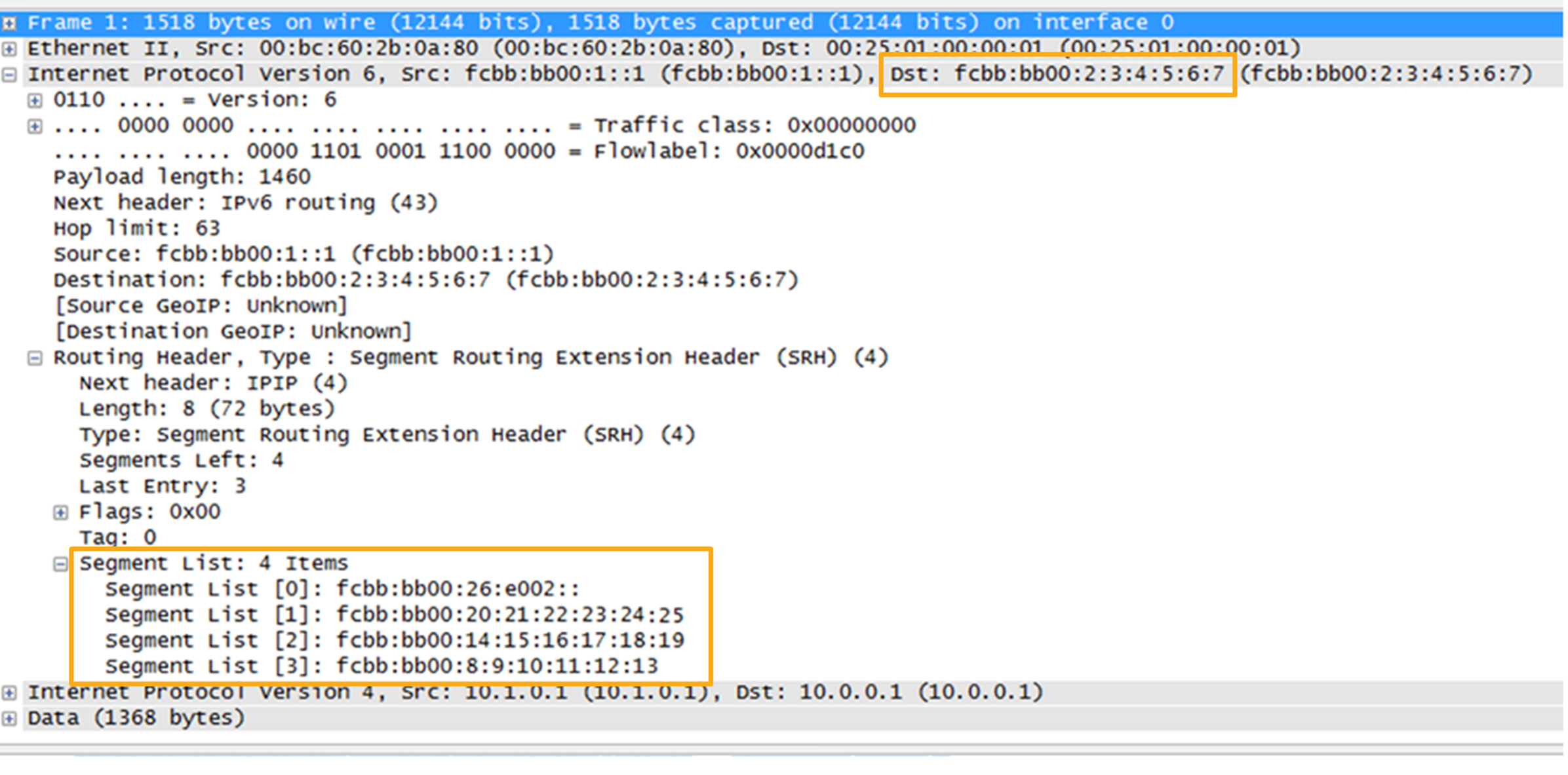 Figure 3: Wireshark display of a captured packet
The packet has an outer IPv6 header with Destination Address fcbb:bb00:2:3:4:5:6:7. This is a uSID container with six uSIDs, the first container as was also shown in the output of Example 3.
The packet contains an SR Routing Header (SRH) with four segments in the Segment List. These four segments are four uSID containers, three of which contain six uSIDs and one containing two uSIDs. Note that the segments in the SRH are encoded in reverse order: last one on top, first one on bottom.
With 6 uSIDs in the IPv6 Destination Address and 20 uSIDs (= 3 × 6 + 1 × 2) this makes a total of 26 uSIDs imposed on the packet.
Conclusion
This report demonstrates the successful validation of line rate insertion of 26 uSID’s on the NCS 5700 Series platforms running Cisco IOS XR.
It demonstrates the ultra-scale capability of the SRv6 solution. 26 is indeed 2 to 3 times better than the current MPLS deployed use-cases.
While reducing the number of layers (MPLS, VxLAN, and NSH are no longer needed), the SRv6 solution provides more power of service expression (Network Programming, Proposed Standard RFC 8986) and ultra-scale.